PipeGlove®, LLC
“Patented”
Removable Pipe Insulation System
Removable Pipe Insulation System
United States Patent
Bond et al.
Patent No: US 10,634,275 B1
Date of Patent: April 28. 2020
(71) Applicants: Brett Bond, Tulsa, OK (US); AlanMilligan, Tulsa, OK
(72) (US)Inventors: Brett Bond, Tulsa, OK (US); AlanMilligan, Tulsa, OK (US)
( *) Notice: Subject to any disclaimer, the term of this patent is extended or adjusted under 35U.S.C. 154(b) by 131 days.
Appl. No.: 15/818,236
Filed: Nov. 20, 2017
( *) Notice: Subject to any disclaimer, the term of this patent is extended or adjusted under 35U.S.C. 154(b) by 131 days.
Appl. No.: 15/818,236
Filed: Nov. 20, 2017
INT. C1
F16L 59/00. (2006.01)
F16L 58/16. (2006.01)
F16L 59/02. (2006.01)
F16L 59/07. (2006.01)
U.S. C1.
CPC…… F16L 58/16 (2013.01); F16L 591022 (2013.01); F16L 591029 (2013.01); F16L 59107 (2013.01)
Field of Classification Search
CPC ……… F16L 55/00; F16L 55/02; F16L 55/022;
F16L 55/023; F16L 55/024; F16L 55/026; F16L 55/029 USPC ……… 138/149, 156, 128, 151, 110; 428/100
See application file for complete search history.
References Cited
U.S. PATENT DOCUMENTS
5,934,337 A * 8/1999 Fiala . Fl6L 59/023…138/149
7,624,762 B2* 12/2009 Cohen B32B 15/08138/149
8,176,943 B2* 5/2012 Stroempl Fl6L 11/125138/133
2004/0079431 Al* 4/2004 Kissell . F16L 59/021138/149
2009/0223585 Al* 9/2009 Buller E03B 7/10138/110
2015/0260329 Al* 9/2015 Bond F16L 59/029428/35.2
*cited by examiner
Primary Examiner – Patrick F Brinson(74) Attorney, Agent, or Firm – Head, Johnson, Kachigian & Wilkinson, PC
ABSTRACT
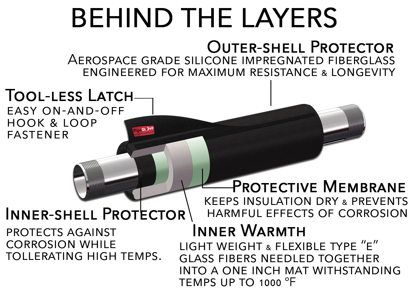
A removable pipe insulation system comprising one or more components, each component comprising insulation in a waterproof covering with at least one opening for air to exit the covering during use. The insulation in the covering may be surrounded by an inside skin with a plurality of holes formed through hot micro perforation. The inside skin may be surrounded by an outside cover, which may be edged in elastic binding and which may attach to itself by hook and loop fastener. The component may be wrapped around a pipe element and secured to provide insulation to the pipe element while protecting the insulation from moisture and protecting the pipe element from corrosion under insulation.
33 Claims, 10 Drawing Sheets

BACKGROUND OF THE INVENTION
Field of the Invention
This invention relates generally to pipe insulation and more particularly, but not by way of limitation, to a system of removable waterproof insulation for pipes.
Description of the Related Art
Insulation, particularly outdoor insulation, is vulnerable to moisture, which may result in a deterioration of insulative value. Traditional insulation wicks moisture, exacerbating any moisture exposure. When the insulation is placed on pipes, moisture in the insulation may also lead to corrosion of the pipes. When wet, chemicals in the insulation react with virtually all metal pipes, causing corrosion under insulation (CUI). Furthermore, traditional insulation is not easily reused. Inspection and service typically renders the existing insulation useless, requiring expensive replacement.
Typically, insulation is placed around a pipe with a heat trace in raw form and is then clad in tin and secured with sheet metal screws. The seams are caulked in an attempt to prevent moisture from reaching the insulation, but this attempt is typically unsuccessful. Any hole in the caulking or the tin, such as along seams and around the screw holes, allows moisture to reach the insulation. The insulation wicks water in, where it reacts with chemicals in the fiberglass, allowing the chemicals to leach out and corrode the underlying pipe. Inspections and repairs require holes to be bored through the tin and into the insulation, providing further points of ingress for moisture.
Modular insulation is known in the art, where insulation is wrapped around pipes and held in place by any of a variety of fasteners. This allows the insulation to be easily removed for inspection and repair, and allows the insulation to be reused if it is still in good condition. These modular systems do not, however, address the moisture problem. The insulation in such modular systems is still vulnerable to moisture, and the non-insulative elements of such systems inadequately protect the insulation from moisture or the underlying pipes from corrosion.
Attempts have been made to seal insulation inside a waterproof casing, but such attempts have produced new challenges. Specifically, given the compressible nature of traditional insulation, air is typically trapped within the waterproof casing along with the insulation. As the insulation is wrapped around a pipe, the air forms a bubble that often makes proper wrapping difficult if not impossible and increases the possibility of rupture of the waterproof casing, allowing moisture to reach the insulation and defeating the purpose of the casing.
Based on the foregoing, it is desirable to provide durable, removable insulation that would stay dry in the worst of outdoor conditions, while still providing easy access to pipes
2
component comprising: insulation; two layers of waterproof material, where the insulation is intermediate of the two layers; at least one opening between the two layers such that air may travel from between the two layers to outside the two layers; and a cover surrounding the two layers. The cover may comprise an inside skin adjacent the first layer of waterproof material and an outside skin adjacent the second layer of waterproof material. Alternately, the pipe insulation system may comprise the insulation surrounded by the cover, and may further comprise the two layers of waterproof material with the insulation intermediate of the two layers.
The pipe insulation system may further comprise a layer of adhesive between the inside skin and first layer of 15waterproof material. The inside skin may be heat resistant to 500° F. The inside skin may have a plurality of holes, which may each have a diameter of 0.025 mm to 1 mm. The plurality of holes may be formed through hot micro perfo-20 ration. The inside skin may be fiberglass coated on one or both sides with silicone.
The two layers of waterproof material may be heat resistant to 400° F. Specifically, the two layers of waterproof material may be nylon. The two layers of waterproof mate-25 rial may form a sleeve with one or two open ends. Each of the ends may be folded over and secured with at least one fastener, such as tape.
The outside cover may be air permeable. The cover may be edged in binding and the binding may be elastic. The pipe 30 insulation system may further comprise one or more attachment devices such that the component may be secured to a pipe element via the attachment devices.
The attachment devices may be areas of hook material and loop material on the cover, such that the component may be secured against itself after being wrapped around the pipe element. Each of the one or more components may be sized and shaped to fit around a particular pipe element. In a second aspect, the invention relates to a method of manufacturing pipe insulation comprising: placing insulation between two layers of waterproof material; partially s sealing the two layers of waterproof material against each other, leaving at least one opening through which air may travel from between the two layers to outside the two layers; and surrounding the insulation between the layers with a cover.
The cover may comprise an inside skin adjacent the first layer and an outside skin adjacent the second layer. The method may further comprise spraying the first layer with adhesive prior to surrounding the insulation between the layers with the cover. The inside skin may have a plurality of holes formed through hot micro perforation. The cover binding, where the binding is elastic.
The two layers of waterproof material may form a sleeve with one or two open ends, and the method may further comprise folding each of the ends over and securing each of the ends with tape.
BRIEF DESCRIPTION OF THE DRAWINGS FIG. 1 is a side partial cutaway view of a pipe insulation component of the present invention in place on a straight pipe element, with one comer raised; FIG. 2 is a cross sectional view of FIG. 1 as indicated by line A; FIG. 3 is a perspective partial cutaway view of the pipe insulation component in place on a straight pipe element, with one comer raised;

